
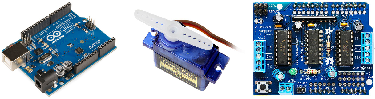
En el siguiente tutorial veremos como hacer un plotter miniatura. Para ello vamos a reciclar dos viejos grabadores de DVD. Necesitaremos además, un servo, el shield para motores de Adafruit y un Arduino UNO R3.
Utilizaremos los grabadores de DVD para mover el plotter en los ejes X e Y. Con un destornillador y un poco de paciencia desmontamos el motor paso a paso junto con el soporte y las guías.
Sobre el motor del eje X montaremos un mecanismo deslizante para sujetar el rotulador. Para ello he retirado la óptica y el láser, y en su lugar he incrustado una tuerca donde atornillar el soporte del rotulador y el servo.
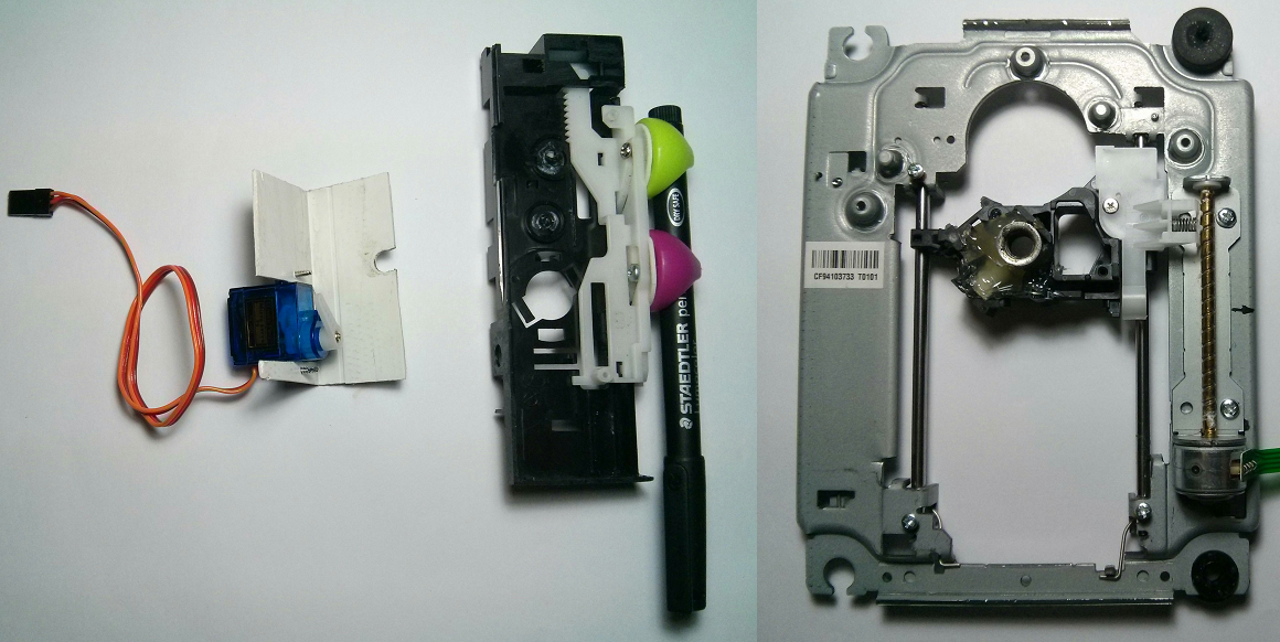

El mecanismo deslizante para el rotulador lo sacaremos de una de las bandejas del grabador de DVD. Para sujetar el servo se puede utilizar un trozo de plástico en forma de L, por ejemplo una canaleta de electricista. Con una sierra y una lima se le puede dar la forma deseada, es un material muy resistente y fácil de trabajar, con él se pueden hacer múltiples piezas de adaptación, pletinas, soportes, etc.
Sobre el motor del eje Y voy a fijar un pequeño soporte para el papel. De igual manera, vamos a retirar la óptica junto con el láser, y a colocar en su lugar dos pequeños separadores donde atornillar una pequeña bandeja para el papel.

Cuando desmontéis el láser, prestad atención a cuatro pequeños imanes que hay junto a la lente. Retiradlos con cuidado, nos servirán para sujetar el papel a la bandeja.
A continuación una imagen del plotter terminado.

Para materializar este proyecto me he basado en éste vídeo del canal de YouTube de Mr. Innovative.
.
Esquema
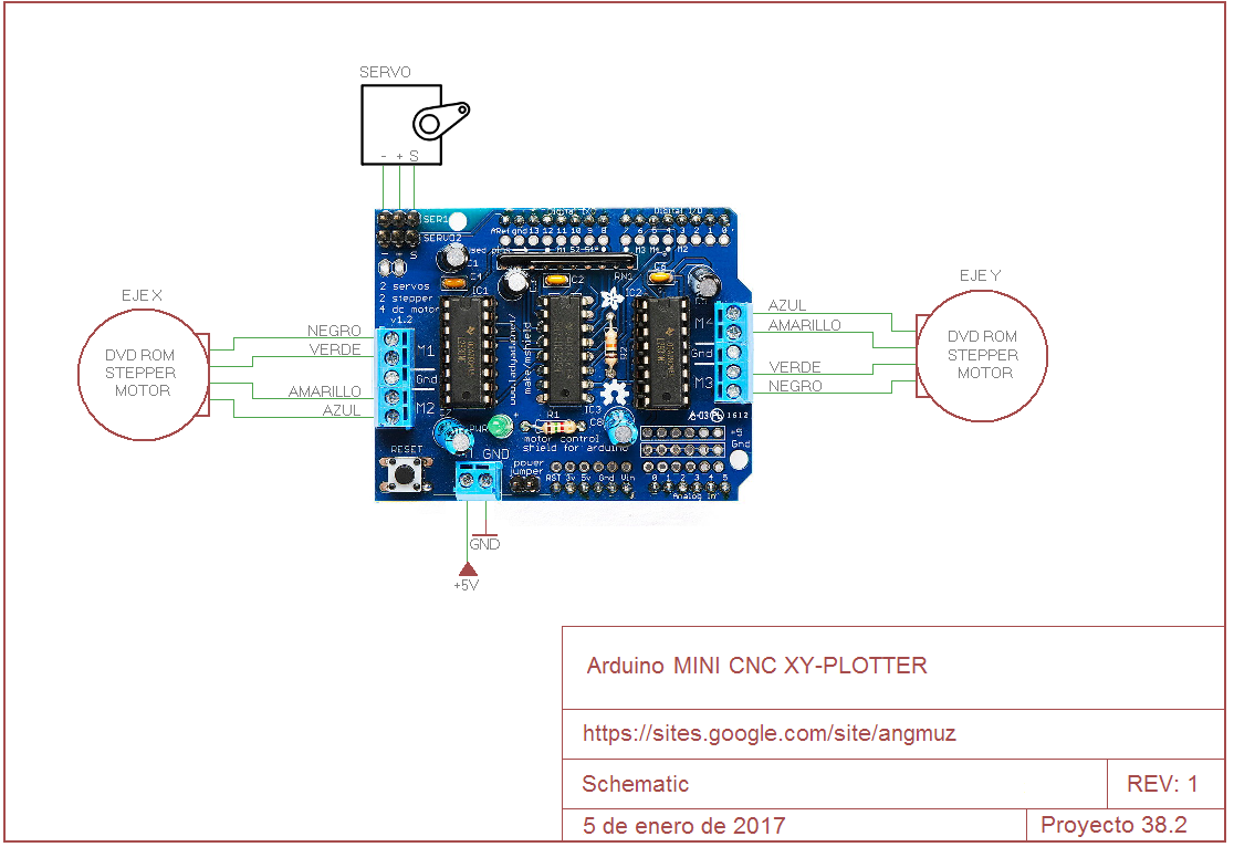
El esquema de conexión es muy sencillo. El motor del eje X se conecta en los terminales marcados como M1 y M2. El motor del eje Y se conecta en los terminales M3 y M4.
El servo para el rotulador se conecta en los pines marcados con Servo 1.
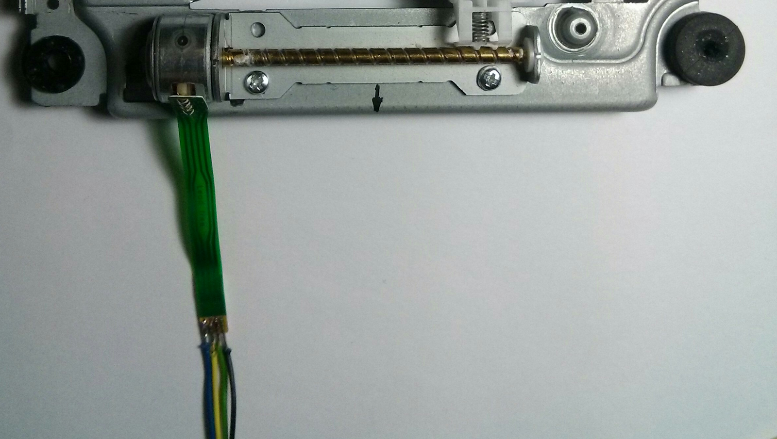
Hay que soldar cuatro hilos a cada motor paso a paso y después conectar cada motor en los terminales correspondientes. Identificar las bobinas de los motores es muy sencillo, basta con medir la impedancia con un polímetro, donde la lectura dé entre 10 y 15 ohmios, ahí tenemos cada una de las bobinas del motor.
No utilizar el puerto USB del ordenador para alimentar el shield, ya que el consumo de ambos motores es mayor de lo que el puerto USB puede suministrar.
Alimentar el circuito a +5V con una fuente de alimentación externa y quitar el jumper.
Sketch
Independientemente de la procedencia de los motores paso a paso utilizados, el código para el Arduino es válido sin hacer grandes cambios. Da igual la marca del grabador de DVD´s utilizado, todos los motores se comportan de manera similar. Incluso se pueden utilizar dos DVD diferentes para montar el CNC.
Para ver si está bien calibrado se puede trazar un segmento de longitud conocida y medirlo. Si la medida corresponde con el tamaño real no hay que calibrar nada. En caso contrario modificar las constantes float StepsPerMillimeterX = 100.0; y float StepsPerMillimeterY = 100.0; hasta que la longitud sobre el papel coincida con la real.
Dependiendo de la orientación del servo y de cómo lo montemos en el soporte, otros parámetros a modificar son const int penZUp = 80; y const int penZDown = 120;
A continuación el código para el Arduino.
/*
Mini CNC Plotter firmware, based in TinyCNC https://github.com/MakerBlock/TinyCNC-Sketches
Send GCODE to this Sketch using gctrl.pde https://github.com/damellis/gctrl
Convert SVG to GCODE with MakerBot Unicorn plugin for Inkscape available here https://github.com/martymcguire/inkscape-unicorn
More information about the Mini CNC Plotter here (german, sorry): http://www.makerblog.at/2015/02/projekt-mini-cnc-plotter-aus-alten-cddvd-laufwerken/
*/
#include <Servo.h>
#include <AFMotor.h>
#define LINE_BUFFER_LENGTH 512
char STEP = MICROSTEP ;
// Servo position for Up and Down
const int penZUp = 80;
const int penZDown = 120;
// Servo on PWM pin 10
const int penServoPin =10 ;
// Should be right for DVD steppers, but is not too important here
const int stepsPerRevolution = 48;
// create servo object to control a servo
Servo penServo;
// Initialize steppers for X- and Y-axis using this Arduino pins for the L293D H-bridge
AF_Stepper myStepperY(stepsPerRevolution,1);
AF_Stepper myStepperX(stepsPerRevolution,2);
/* Structures, global variables */
struct point {
float x;
float y;
float z;
};
// Current position of plothead
struct point actuatorPos;
// Drawing settings, should be OK
float StepInc = 1;
int StepDelay = 1;
int LineDelay =0;
int penDelay = 50;
// Motor steps to go 1 millimeter.
// Use test sketch to go 100 steps. Measure the length of line.
// Calculate steps per mm. Enter here.
float StepsPerMillimeterX = 100.0;
float StepsPerMillimeterY = 100.0;
// Drawing robot limits, in mm
// OK to start with. Could go up to 50 mm if calibrated well.
float Xmin = 0;
float Xmax = 40;
float Ymin = 0;
float Ymax = 40;
float Zmin = 0;
float Zmax = 1;
float Xpos = Xmin;
float Ypos = Ymin;
float Zpos = Zmax;
// Set to true to get debug output.
boolean verbose = false;
// Needs to interpret
// G1 for moving
// G4 P300 (wait 150ms)
// M300 S30 (pen down)
// M300 S50 (pen up)
// Discard anything with a (
// Discard any other command!
/**********************
* void setup() - Initialisations
***********************/
void setup() {
// Setup
Serial.begin( 9600 );
penServo.attach(penServoPin);
penServo.write(penZUp);
delay(100);
// Decrease if necessary
myStepperX.setSpeed(600);
myStepperY.setSpeed(600);
// Set & move to initial default position
// TBD
// Notifications!!!
Serial.println("Mini CNC Plotter alive and kicking!");
Serial.print("X range is from ");
Serial.print(Xmin);
Serial.print(" to ");
Serial.print(Xmax);
Serial.println(" mm.");
Serial.print("Y range is from ");
Serial.print(Ymin);
Serial.print(" to ");
Serial.print(Ymax);
Serial.println(" mm.");
}
/**********************
* void loop() - Main loop
***********************/
void loop()
{
delay(100);
char line[ LINE_BUFFER_LENGTH ];
char c;
int lineIndex;
bool lineIsComment, lineSemiColon;
lineIndex = 0;
lineSemiColon = false;
lineIsComment = false;
while (1) {
// Serial reception - Mostly from Grbl, added semicolon support
while ( Serial.available()>0 ) {
c = Serial.read();
if (( c == '\n') || (c == '\r') ) { // End of line reached
if ( lineIndex > 0 ) { // Line is complete. Then execute!
line[ lineIndex ] = '\0'; // Terminate string
if (verbose) {
Serial.print( "Received : ");
Serial.println( line );
}
processIncomingLine( line, lineIndex );
lineIndex = 0;
}
else {
// Empty or comment line. Skip block.
}
lineIsComment = false;
lineSemiColon = false;
Serial.println("ok");
}
else {
if ( (lineIsComment) || (lineSemiColon) ) { // Throw away all comment characters
if ( c == ')' ) lineIsComment = false; // End of comment. Resume line.
}
else {
if ( c <= ' ' ) { // Throw away whitepace and control characters
}
else if ( c == '/' ) { // Block delete not supported. Ignore character.
}
else if ( c == '(' ) { // Enable comments flag and ignore all characters until ')' or EOL.
lineIsComment = true;
}
else if ( c == ';' ) {
lineSemiColon = true;
}
else if ( lineIndex >= LINE_BUFFER_LENGTH-1 ) {
Serial.println( "ERROR - lineBuffer overflow" );
lineIsComment = false;
lineSemiColon = false;
}
else if ( c >= 'a' && c <= 'z' ) { // Upcase lowercase
line[ lineIndex++ ] = c-'a'+'A';
}
else {
line[ lineIndex++ ] = c;
}
}
}
}
}
}
void processIncomingLine( char* line, int charNB ) {
int currentIndex = 0;
char buffer[ 64 ]; // Hope that 64 is enough for 1 parameter
struct point newPos;
newPos.x = 0.0;
newPos.y = 0.0;
// Needs to interpret
// G1 for moving
// G4 P300 (wait 150ms)
// G1 X60 Y30
// G1 X30 Y50
// M300 S30 (pen down)
// M300 S50 (pen up)
// Discard anything with a (
// Discard any other command!
while( currentIndex < charNB ) {
switch ( line[ currentIndex++ ] ) { // Select command, if any
case 'U':
penUp();
break;
case 'D':
penDown();
break;
case 'G':
buffer[0] = line[ currentIndex++ ]; // /!\ Dirty - Only works with 2 digit commands
// buffer[1] = line[ currentIndex++ ];
// buffer[2] = '\0';
buffer[1] = '\0';
switch ( atoi( buffer ) ){ // Select G command
case 0: // G00 & G01 - Movement or fast movement. Same here
case 1:
// /!\ Dirty - Suppose that X is before Y
char* indexX = strchr( line+currentIndex, 'X' ); // Get X/Y position in the string (if any)
char* indexY = strchr( line+currentIndex, 'Y' );
if ( indexY <= 0 ) {
newPos.x = atof( indexX + 1);
newPos.y = actuatorPos.y;
}
else if ( indexX <= 0 ) {
newPos.y = atof( indexY + 1);
newPos.x = actuatorPos.x;
}
else {
newPos.y = atof( indexY + 1);
indexY = '\0';
newPos.x = atof( indexX + 1);
}
drawLine(newPos.x, newPos.y );
// Serial.println("ok");
actuatorPos.x = newPos.x;
actuatorPos.y = newPos.y;
break;
}
break;
case 'M':
buffer[0] = line[ currentIndex++ ]; // /!\ Dirty - Only works with 3 digit commands
buffer[1] = line[ currentIndex++ ];
buffer[2] = line[ currentIndex++ ];
buffer[3] = '\0';
switch ( atoi( buffer ) ){
case 300:
{
char* indexS = strchr( line+currentIndex, 'S' );
float Spos = atof( indexS + 1);
// Serial.println("ok");
if (Spos == 30) {
penDown();
}
if (Spos == 50) {
penUp();
}
break;
}
case 114: // M114 - Repport position
Serial.print( "Absolute position : X = " );
Serial.print( actuatorPos.x );
Serial.print( " - Y = " );
Serial.println( actuatorPos.y );
break;
default:
Serial.print( "Command not recognized : M");
Serial.println( buffer );
}
}
}
}
/*********************************
* Draw a line from (x0;y0) to (x1;y1).
* Bresenham algo from https://www.marginallyclever.com/blog/2013/08/how-to-build-an-2-axis-arduino-cnc-gcode-interpreter/
* int (x1;y1) : Starting coordinates
* int (x2;y2) : Ending coordinates
**********************************/
void drawLine(float x1, float y1) {
if (verbose)
{
Serial.print("fx1, fy1: ");
Serial.print(x1);
Serial.print(",");
Serial.print(y1);
Serial.println("");
}
// Bring instructions within limits
if (x1 >= Xmax) {
x1 = Xmax;
}
if (x1 <= Xmin) {
x1 = Xmin;
}
if (y1 >= Ymax) {
y1 = Ymax;
}
if (y1 <= Ymin) {
y1 = Ymin;
}
if (verbose)
{
Serial.print("Xpos, Ypos: ");
Serial.print(Xpos);
Serial.print(",");
Serial.print(Ypos);
Serial.println("");
}
if (verbose)
{
Serial.print("x1, y1: ");
Serial.print(x1);
Serial.print(",");
Serial.print(y1);
Serial.println("");
}
// Convert coordinates to steps
x1 = (int)(x1*StepsPerMillimeterX);
y1 = (int)(y1*StepsPerMillimeterY);
float x0 = Xpos;
float y0 = Ypos;
// Let's find out the change for the coordinates
long dx = abs(x1-x0);
long dy = abs(y1-y0);
int sx = x0<x1 ? StepInc : -StepInc;
int sy = y0<y1 ? StepInc : -StepInc;
long i;
long over = 0;
if (dx > dy) {
for (i=0; i<dx; ++i) {
myStepperX.onestep(sx,STEP);
over+=dy;
if (over>=dx) {
over-=dx;
myStepperY.onestep(sy,STEP);
}
delay(StepDelay);
}
}
else {
for (i=0; i<dy; ++i) {
myStepperY.onestep(sy,STEP);
over+=dx;
if (over>=dy) {
over-=dy;
myStepperX.onestep(sx,STEP);
}
delay(StepDelay);
}
}
if (verbose)
{
Serial.print("dx, dy:");
Serial.print(dx);
Serial.print(",");
Serial.print(dy);
Serial.println("");
}
if (verbose)
{
Serial.print("Going to (");
Serial.print(x0);
Serial.print(",");
Serial.print(y0);
Serial.println(")");
}
// Delay before any next lines are submitted
delay(LineDelay);
// Update the positions
Xpos = x1;
Ypos = y1;
}
// Raises pen
void penUp() {
penServo.write(penZUp);
delay(penDelay);
Zpos=Zmax;
digitalWrite(15, LOW);
digitalWrite(16, HIGH);
if (verbose) {
Serial.println("Pen up!");
}
}
// Lowers pen
void penDown() {
penServo.write(penZDown);
delay(penDelay);
Zpos=Zmin;
digitalWrite(15, HIGH);
digitalWrite(16, LOW);
if (verbose) {
Serial.println("Pen down.");
}
}
A partir de aquí el funcionamiento del plotter es igual que el del Proyecto 38.1. Una vez programado el Arduino necesitamos el archivo que contiene el dibujo que debe trazar el plotter y además un software que envíe los datos del archivo al Arduino, a través del puerto COM.
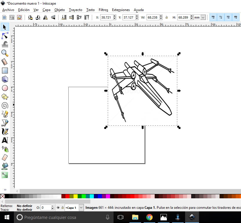
Los archivos con el dibujo a trazar son archivos con extensión gcode. Estos archivos se generan partiendo de la imagen que queremos dibujar en formato JPG, BMP, PNG, etc… y con el programa InkScape la convertimos a gcode, mediante un proceso llamado vectorización.
El siguiente vídeo explica cómo convertir una imagen en un archivo gcode. Si tu ordenador trabaja con Windows XP, la versión de Inkscape debe ser la 0.48.5. La puedes descargar aquí.
Cuando escribo estas líneas, para W10 la versión actual de Inkscape es la v0.91. La puedes descargar aquí.
Esta versión de Inkscape de un error a la hora de salvar el archivo en formato gcode. Para solucionarlo hay que seleccionar “px” en unidades en lugar de “mm” en las propiedades del documento.
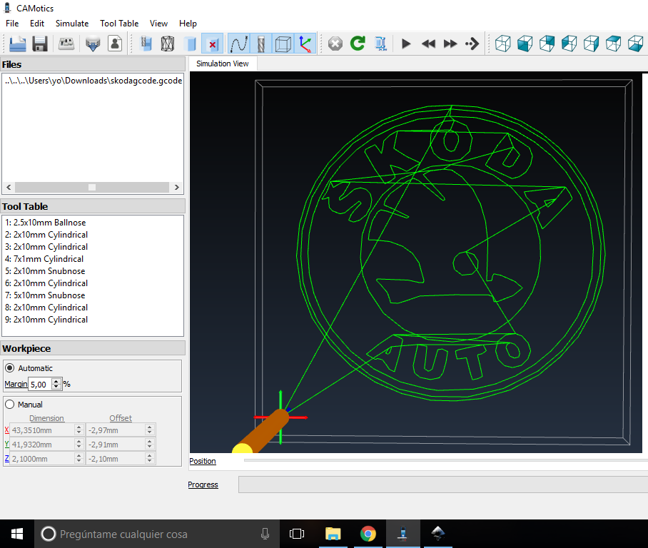
Una vez tenemos el archivo gcode creado, podemos simular su funcionamiento con el software CAMotics. Viene explicado en el vídeo anterior. Para que el plotter trace el dibujo correctamente, la simulación debe quedar como en la imagen siguiente, es decir, el cursor en la esquina inferior izquierda y el offset negativo y de pequeño valor.
En el caso de que la simulación quede un offset elevado y el cursor en el centro, lo más seguro es que el dibujo quede recortado en el plotter. Mira el ejemplo siguiente.

Para solucionar este problema, probad a desplazar la imagen hacia una esquina en el InkScape, no pasa nada si queda fuera del documento. Guardar el archivo y abrirlo con el CAMotics, haced pruebas hasta que salga bien.
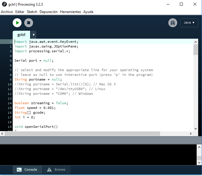
Una vez tenemos el archivo gcode correctamente vectorizado, lo siguiente es enviarlo al Arduino mediante una herramienta llamada Processing, se puede descargar aquí.
Instalar Processing y abrirlo. Para enviar el archivo gcode, necesitamos una interfaz gráfica de usuario llamada Gctrl.pde disponible para descargar aquí.
Ir a Archivo→Abrir→Gcontrol→source→gctrl.pde
Se abrirá una ventana como la siguiente:
Hacer clic en el icono Play, aparece el siguiente menú:
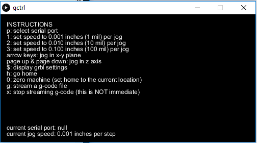
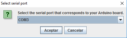
Pulsar p (en minúsculas) para seleccionar el puerto COM del Arduino. Si no responde, click en Stop y de nuevo en Play.
Pulsar g para seleccionar el archivo gcode con el dibujo. Tan pronto como pulsemos Enter, el plotter comenzará a trazar el dibujo.
Links
Canal YouTube de Mr. Innovative, How to make Mini CNC plotter machine
Instructables, How to Make Arduino Based Mini CNC Plotter
Mini CNC Plotter firmware, based in TinyCNC
Convert SVG to GCODE with Maker Bot Unicorn plugin for Inkscape.
Special Thanks to Marty McGuire for his help in debugging the creation of gcode files with Inkscape.
Más información sobre Mini Plotter CNC aquí (en alemán)
No hay comentarios.:
Publicar un comentario